25-Year Field Life: Solar Stamped Electrical Terminals Validation Guide
A PV junction box terminal that passes factory testing at 25°C can fail after 10 years of daily thermal cycling from -40°C to +85°C. The failure surfaces only after string-level power loss triggers a costly field replacement campaign.
In this guide, you will learn tin whisker prevention, IEC 61215 compliance, and accelerated life testing protocols for 25-year field exposure. You will also find material selection criteria for daily thermal cycling and UV exposure.
Read on for the full validation guide.
Thermal Cycling and Environmental Exposure
Solar terminals operate in an environment that cycles between extremes every 24 hours. A rooftop junction box in Arizona sees daytime internal temperatures exceeding 85°C followed by nighttime lows near -20°C, with the terminal experiencing this full swing 365 times per year. Over a 25-year module warranty period, the terminal endures over 9,000 thermal cycles.
Each cycle stresses the interface between the tin-plated terminal and the copper ribbon or wire crimp through differential expansion — brass at 20 µm/m·°C and copper at 17 µm/m·°C driving micro-motion at the contact interface. This fretting progressively oxidizes the tin surface, increasing contact resistance by 0.5–2 milliohms per year in the absence of adequate normal force retention.
Condensation adds a second failure vector. Modules cool below the dew point at night, drawing moisture into the junction box through the cable gland and condensing directly on the terminal surface. This moisture, combined with residual flux from the soldering or crimping process, creates a localized galvanic cell that corrodes the terminal base metal within 3–5 years in coastal installations.
Humidity-freeze cycling per IEC 61215-2 MQT 12 accelerates this mechanism: 10 cycles from 85°C at 85% relative humidity to -40°C expose any plating void or crimp defect that would otherwise remain hidden during factory-level testing at ambient conditions.
Material Selection for Durability
Junction box terminals form the highest-volume solar terminal category. A standard 72-cell module houses three junction boxes, each containing four to six stamped terminals that connect bypass diodes to the ribbon conductors exiting the laminate. These terminals use brass C26000 strip 0.4–0.6 mm thick with a solderable tin finish over a nickel barrier.
The key engineering constraint is solderability retention: after sitting in inventory for six months and surviving the lamination process at 150°C for 15 minutes, the terminal must still wet fully within 2 seconds during wave soldering to the ribbon. This demands a tin plating thickness of 3–5 µm minimum with a co-deposited organic brightener that resists thermal degradation during the module’s post-lamination annealing step.
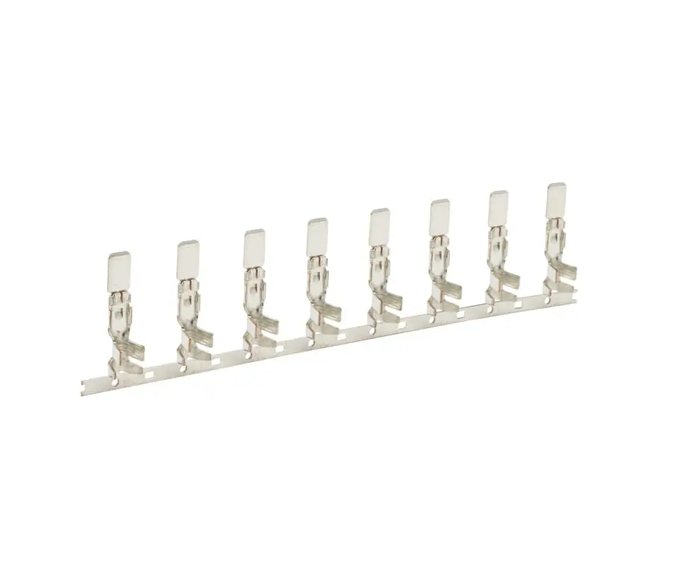
MC4-style connector terminals represent a higher-performance tier. These cylindrical stamped-and-formed contacts operate at 20–30 A continuous current with peak voltages reaching 1,500 V in utility-scale string architectures. The contact beam must maintain insertion and withdrawal forces within the 10–50 N range across 50 mating cycles after 2,000 thermal cycles, ruling out pure brass and driving selection toward phosphor bronze C51000 or beryllium copper C17200 for the spring element.
Tracker-mounted PV systems add a mechanical dimension: connectors on single-axis trackers experience 0.3–0.5 mm of daily micro-motion at the terminal level due to wind-induced panel deflection. This fretting motion accelerates tin oxide wear at the contact interface, making selective gold plating on the mating zone a cost-justified upgrade for projects targeting sub-0.5% annual degradation rates.
[Compliance Anchor]: Stamped terminals for PV junction boxes must show contact resistance change below 1 milliohm after 2,000 thermal cycles from -40°C to +85°C per IEC 61215-2 MQT 11.2, measured at the wire-to-terminal crimp interface before and after cycling.
💡 Thermal Cycling Validation Gap: Factory-passing terminals with inadequate normal force retention can drift 0.5–2 milliohms per year in the field — request a thermal cycling qualification test on your production junction box assembly before committing to a terminal design.
Certification Landscape
Solar module certification follows a two-track system that converges at the terminal level. IEC 61215 governs module design qualification and type approval for crystalline silicon PV modules, specifying the thermal cycling, humidity-freeze, and damp heat test sequences that stress every component inside the junction box. UL 1703 covers flat-plate PV modules for the North American market and requires additional testing for fire resistance and bonding path continuity through the terminal.
A terminal supplier serving both markets must deliver terminals that pass IEC 61215-2 MQT 11 through 13 while also maintaining the ground continuity resistance below 0.1 ohm required by UL 1703 section 24.
Tin Whisker and MLPE Requirements
Tin whisker risk introduces a certification challenge unique to solar. Pure tin plating — the default cost-effective finish for brass terminals — grows conductive whiskers under the compressive stress of the crimp joint over multi-year timeframes. JEDEC JESD201 mandates a nickel underlayer of 1.2 µm minimum thickness to suppress whisker growth.
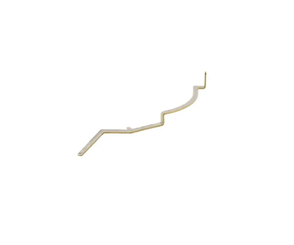
Terminals destined for module-level power electronics (MLPE) such as microinverters and DC optimizers face an additional requirement: the fine-pitch spacing inside these compact enclosures makes even a sub-millimeter whisker a short-circuit risk, demanding 100% whisker mitigation through nickel barrier plating rather than relying on post-plating annealing alone.
Material declaration under EU RoHS and REACH forms the baseline compliance layer for solar metal stamping for EU-bound modules. Beyond substance restrictions, module manufacturers increasingly require suppliers to provide full material disclosure per IPC-1752A, listing every substance in the terminal alloy, plating, and any post-treatment chemistry used during manufacturing.
[Compliance Anchor]: Solar terminal suppliers must deliver terminals that pass IEC 61215-2 thermal cycling and humidity-freeze sequences on the customer’s production-representative junction box assembly, not only on bare terminals — the interaction between terminal, diode, encapsulant, and housing materials changes the failure signature compared to component-level testing.
Solar Stamped Terminal Archetypes
MLPE terminals inside microinverters and DC optimizers operate at the intersection of power electronics and outdoor exposure. These stamped terminals feed current from the module leads into a sealed electronics enclosure, where they solder directly to the PCB or plug into a board-mounted header. The terminal must survive the same thermal cycling as a junction box terminal while also maintaining solder joint integrity under the vibration induced by roof-mounted inverters switching at 20–100 kHz.
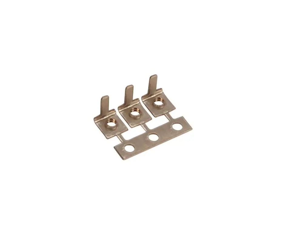
Each of these solar industry terminal types shares a common requirement: accelerated life test data that proves the terminal survives 25 years of field exposure, with every data point traceable to a specific production lot and test report.
[Compliance Anchor]: Solderability per J-STD-002 requires that 95% of the terminal’s solderable surface area wet within 2 seconds after 8 hours of steam aging — a requirement that demands documented tin plating bath chemistry control logs traceable to each production lot.
💡 Plating Bath Consistency Audit: Solderability failures trace to plating bath chemistry drift weeks before mechanical dimensions show any change — submit your terminal solderability specification for a process capability study covering tin thickness, nickel barrier integrity, and steam aging performance.
Field Life Assurance
Accelerated Life Test Protocol
A terminal lot that passes factory electrical testing tells you nothing about year-10 performance without accelerated life data. Kravzik validates solar terminal designs using a sequenced test protocol that combines IEC 61215-2 thermal cycling, humidity-freeze, and damp heat exposure on production-representative junction box assemblies. Every test sequence runs on terminals pulled from three separate production lots, eliminating the risk that a single golden lot passes while production variation would cause field failures.
Contact resistance is measured at the wire crimp interface before and after each stress sequence using a four-wire Kelvin measurement at 1 A test current, providing milliohm-level resolution that detects early-stage fretting corrosion before it becomes a field failure.
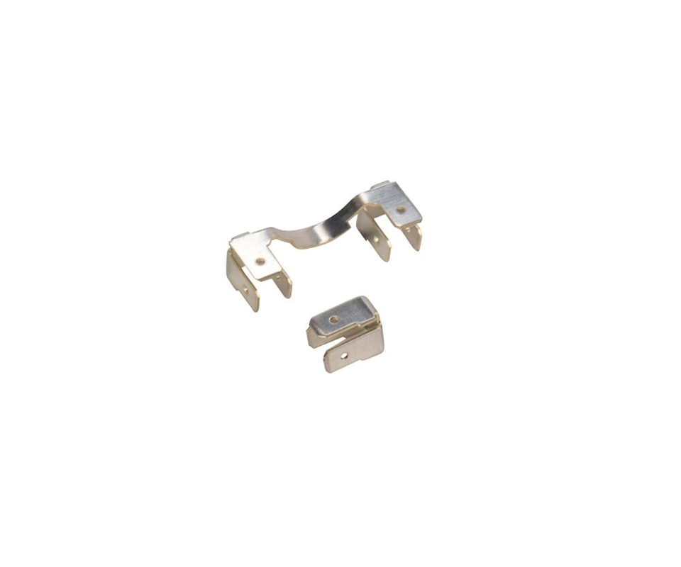
Material traceability forms the second pillar of solar terminal reliability. Tin plating process control for solar terminals requires documented plating bath chemistry logs, X-ray fluorescence thickness measurements at five points per strip, and cross-sectional metallography confirming the nickel barrier layer thickness exceeds 1.2 µm at the thinnest point. Each reel of finished terminals carries a lot identification code linking to the specific brass coil heat number, plating bath ID, and inspection data file, enabling module manufacturers to satisfy IEC 62941 traceability requirements without performing incoming inspection on every terminal lot.
[Compliance Anchor]: Accelerated life testing for solar terminals must demonstrate zero contact resistance drift exceeding 1 milliohm after the full IEC 61215-2 test sequence executed on a minimum of 30 terminals drawn from 3 production lots — a sample size sufficient to detect a 10% defect rate with 95% confidence per IEC 61215-1 section 8.3.
Compliance Pass
A PV module passing IEC 61215 type approval can fail when production lots from different plating batches introduce contact resistance drift years into field operation. Kravzik stamps solar-grade terminals with full lot traceability, shipping every lot with XRF reports linked to IEC 61215-2 qualification data.
Send us your terminal specifications for a PV qualification test package, delivered with lot-level traceability and IEC 61215-validated field life data.
Related Engineering Resources
- Copper alloy selection for PV connector spring contacts with thermal cycling data in copper alloy material property reference
- Selective gold plating for high-cycle PV connector contacts requiring sub-milliohm stability across 50 mating cycles in gold and silver plating process capabilities
- High-volume reel-to-reel stamping and plating for solar terminal production at 50 million+ units per year in high-volume metal stamping services