High-Current Reliability: Electrical Stamped Electrical Terminals Engineering Guide
A busbar terminal carrying 200 A can enter thermal runaway when contact resistance drifts upward by only 2 milliohms. A micro-void in the plating triggers a heating-oxidation-resistance feedback loop that ends with a charred bushing and unscheduled shutdown after 18 months of load cycling.
In this guide, you will learn thermal rise validation for high-current stamped terminals in switchgear. You will also find IEC 61439 compliance and plating criteria that prevent hot spots above 100 A.
Read on for the full engineering guide.
Thermal & Current Stress
Electrical power terminals operate at current levels that make contact resistance a thermal management problem rather than a signal integrity concern. A stamped copper terminal in a 630 A feeder circuit carries enough current that each microhm of contact resistance dissipates 0.4 W.
At a bolted busbar interface with six M8 fasteners, the contact resistance across the joint typically measures 3–5 microhms when clean and properly torqued. After two years of daily load cycling from 30% to 100% of rated current, differential thermal expansion between the copper terminal and the aluminum busbar loosens the bolt preload by 15–30%.
Contact Resistance and Thermal Escalation
This bolt preload relaxation increases the contact resistance to 15–25 microhms, raising the joint temperature from 105°C to above 140°C. The temperature exceeds the 65 K rise limit defined by IEC 61439-1 and degrades the silver plating through accelerated oxidation at the bolted interface.
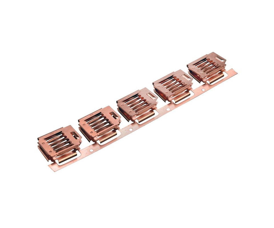
Short-circuit withstand imposes a different failure mode from steady-state thermal behavior. During a fault condition, the terminal must carry 10–20 times its rated current for up to 1 second without the contact interface welding together under the electromagnetic forces between parallel conductors.
The peak let-through current generates instantaneous temperatures exceeding 200°C at the contact asperities, where current constriction concentrates heat into micron-scale hot spots. Silver plating melts at these temperatures, allowing copper-to-copper contact that welds the joint — converting a bolted connection into a permanent bond that cannot be disassembled for maintenance. Terminals that pass thermal rise testing at rated current can still fail short-circuit withstand if the contact surface area is inadequate for the magnetic repulsion forces between adjacent phases.
[Compliance Anchor]: Stamped terminals for power distribution assemblies must pass IEC 61439-1 thermal rise testing with temperature measured at the hottest accessible point of the bolted joint — not at the terminal body away from the contact interface, which understates the true hot-spot temperature by 20–30 K in multi-bolt busbar connections.
💡 Thermal Rise Validation Gap: Terminals qualified at room temperature can develop hot spots within 18–24 months of thermal cycling under load — long after commissioning thermography clears the assembly. request a thermal rise simulation for your stamped terminal geometry at rated current before locking the material specification.
Switchgear Standards Framework
IEC 61439 forms the design and verification framework for low-voltage switchgear and controlgear assemblies, with Part 1 defining the mandatory type tests that component suppliers must support. Thermal rise testing per section 10.10 requires the terminal to operate at rated current until temperatures stabilize, with thermocouples placed at every bolted joint and contact interface.
The 65 K rise limit applies at the hottest measured point, not as an average across the terminal. This single-point measurement requirement drives terminal geometry decisions: a terminal with uniform cross-section that avoids current constriction at the bolt hole naturally produces a more even temperature distribution than a stamped terminal with sharp internal corners that concentrate current density.
Dielectric Integrity and Creepage Verification
Creepage and clearance distances per IEC 60664-1 govern the minimum spacing between terminals at different phases and between terminals and grounded metal. For a 690 VAC system at pollution degree 3, the minimum creepage distance is 8 mm.
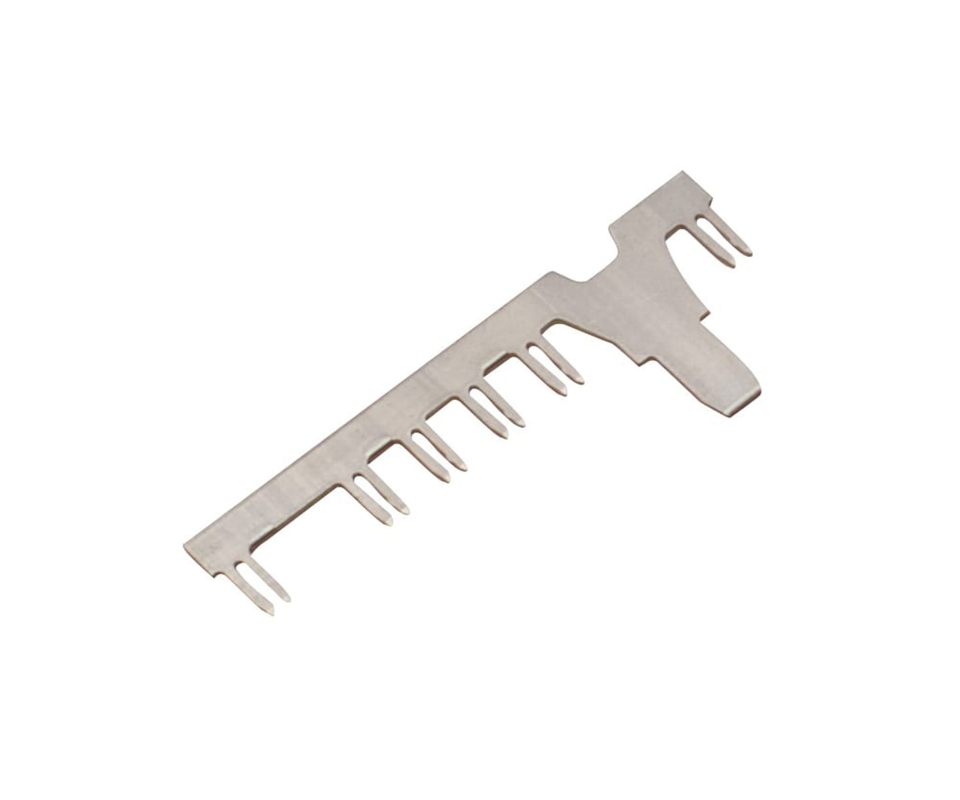
Stamped terminals in compact switchgear designs often violate this requirement when the terminal’s formed geometry brings the edge of the terminal closer to an adjacent phase than the straight-line distance measured on the busbar. The formed radius at the terminal end can reduce the effective creepage path by 2–3 mm compared to the design intent, requiring a rib or barrier feature that the stamping tooling must form without cracking the material at the bend line.
For electrical metal stamping suppliers in the North American market, UL 486A-486B governs wire connector and terminal qualification for use in UL 508A industrial control panels. These standards require pull-out force testing on crimped connections and thermal cycling on bolted joints, providing the component-level qualification data that panel builders reference in their UL file.
[Compliance Anchor]: Terminal assemblies must pass dielectric voltage-withstand testing at 2,500 VAC for 1 minute per IEC 61439-1 section 10.9 after thermal cycling, with no flashover or breakdown — thermal relaxation of the terminal geometry can reduce creepage distances below the design minimum, causing dielectric failure at test voltages far below the terminal’s rated insulation level.
Stamped Terminal Archetypes in Power Distribution
Power distribution stamped terminals span from busbar interconnection blocks carrying hundreds of amps to fuse clip contacts that must survive repeated insertion cycles. Each archetype imposes distinct electrical, mechanical, and plating demands that stamping tooling and material selection must address.
Busbar and Circuit Breaker Terminal Design
Busbar interconnection terminals form the highest-current category in electrical distribution. These stamped copper terminals bolt directly to aluminum or copper busbars inside switchgear cubicles, carrying 100–630 A with temperature rise limits dictating the required cross-section.
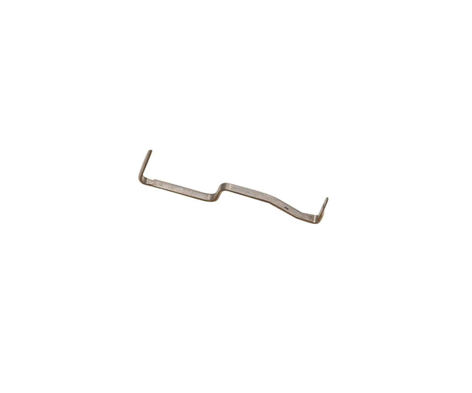
A copper C11000 terminal 5 mm thick and 30 mm wide provides 150 mm² of cross-section — sufficient for 400 A at a 65 K rise when the bolted joint contact resistance stays below 5 microhms. Silver plating at 5 µm minimum thickness provides the low-resistance interface and prevents copper oxidation at operating temperatures up to 130°C.
The terminal’s formed geometry must include a curved transition from the flat bolting pad to the wire crimp barrel, avoiding sharp 90° bends that concentrate stress and initiate fatigue cracking under the 100 Hz vibration transmitted from the switchgear’s magnetic contactors.
Circuit breaker terminals operate at the intersection of normal current carrying and fault interruption. A molded case circuit breaker rated 250 A uses stamped copper terminals with silver-plated line and load connections that bolt to the panel busbar and the load cable lug respectively.
The terminal must survive both the steady-state temperature rise at rated current and the instantaneous electromagnetic forces during a 25 kA fault — forces that reach 500 N between adjacent phases in a compact breaker, attempting to bend the terminal away from its mounting location. The terminal’s cross-section design must account for both the thermal requirement and the mechanical requirement, with the mechanical constraint typically driving a thicker cross-section than the electrical-thermal calculation alone would suggest.
Fuse Holder and Disconnect Contact Endurance
Fuse holder terminals and disconnect switch contacts represent a third category where mating durability intersects with current rating. These energy industry terminals must survive 100 insertion-withdrawal cycles of a fuse cartridge while maintaining contact resistance below 10 microhms.
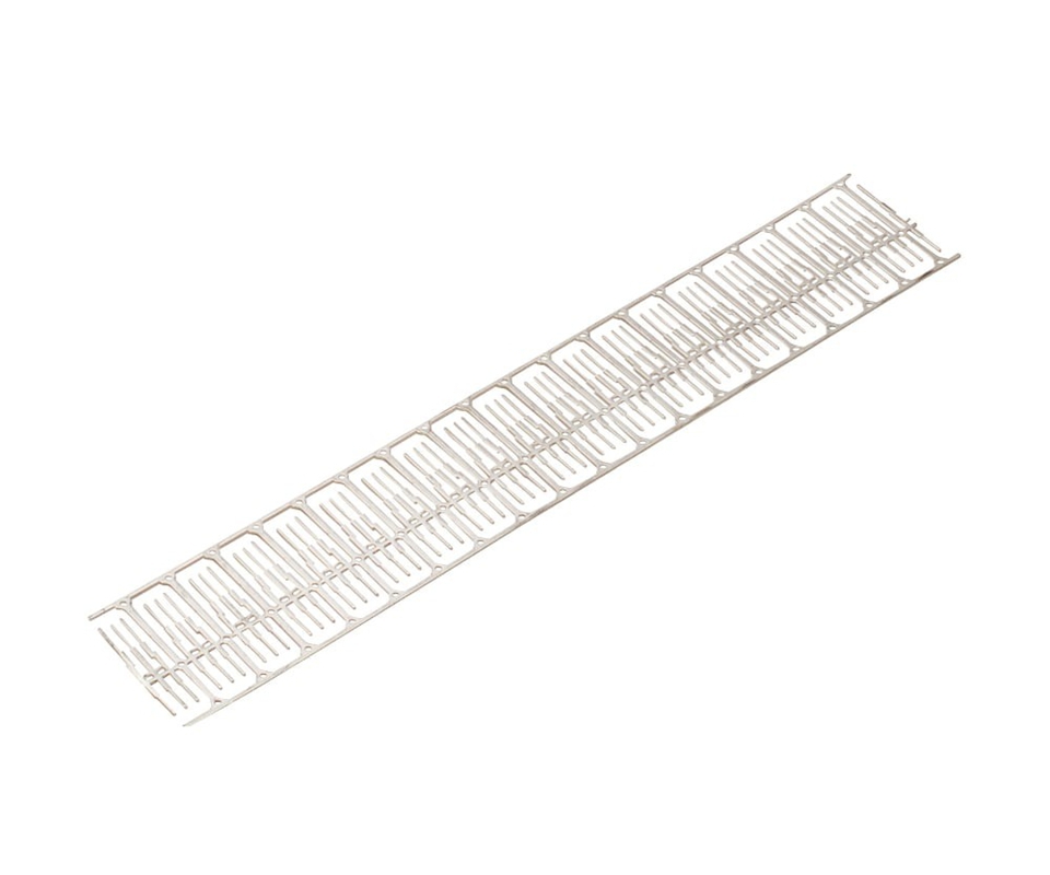
Each insertion scrapes a fraction of a micron from the silver plating, and after 100 cycles the cumulative wear exposes high spots of copper that oxidize and increase resistance. This wear mechanism demands a silver plating thickness of 8–10 µm minimum on fuse clip contacts — twice the thickness required for a stationary bolted joint carrying the same current.
[Compliance Anchor]: Fuse clip terminals must demonstrate contact resistance below 10 microhms after 100 insertion-withdrawal cycles measured at 50% of fuse rated current, using a production fuse cartridge — testing with a polished steel test blade produces artificially low wear and does not represent the abrasive action of an actual fuse end cap with its as-manufactured surface roughness.
💡 Terminal Selection for Your Assembly: The stamped terminal cross-section must account for both continuous current and fault withstand — thermal-only sizing risks mechanical failure during short-circuit events. submit your busbar specifications for a terminal recommendation validated against your specific fault current rating.
Plating & Contact Life
Silver plating for power terminals differs fundamentally from decorative silver finishing. The functional silver layer must be 5 µm minimum applied directly over copper or over a thin nickel barrier that prevents copper diffusion into the silver at operating temperatures above 100°C.
Copper diffusion without a barrier layer creates a copper-silver intermetallic at the interface that increases the joint resistance by 10–20 microhms over 5–7 years of continuous operation at elevated temperature.
Silver Plating Specification and Joint Flatness
X-ray fluorescence measurement at three points per terminal — at the bolt contact zone, the bend transition, and the crimp barrel — verifies thickness distribution and detects the thin spots that develop at the bend line where the electroplating current density was lower during deposition.
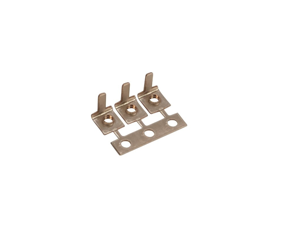
Bolted joint design completes the contact resistance equation. The terminal’s flat contact pad must achieve a surface flatness of 0.05 mm across the bolt contact zone, verified with a dial indicator during incoming inspection.
A convex pad surface concentrates the bolt clamping force at a single line of contact rather than distributing it across the full pad area, reducing the effective contact area by 40–60% and driving up the joint resistance. Kravzik maintains this flatness through precision metal stamping with a coining station that flattens the bolt contact zone to within 0.03 mm of true flat, eliminating the curvature introduced by the stamping punch’s breakout angle at the blanked edge.
[Compliance Anchor]: Silver-plated power terminals must demonstrate zero copper diffusion to the plating surface after 1,000 hours at 130°C per ASTM B571 section 9, verified by cross-sectional SEM-EDS analysis at the bolt contact zone — the highest-temperature location on the terminal during rated current operation.
Compliance Pass
Switchgear passing type testing with qualification lots can develop thermal hot spots from production lots stamped from different coils and plated in different baths. Kravzik stamps power distribution terminals with in-line coining, shipping every lot with silver plating XRF reports, contact resistance data, and IEC 61439-1 thermal rise certificates.
Send us your terminal requirements for a power distribution qualification package, including IEC 61439 thermal rise and short-circuit withstand data.
Related Engineering Resources
- Copper C11000 conductivity data and silver plating adhesion requirements in copper alloy material property reference
- Silver and tin plating for bolted power connections with thermal cycling validation in industrial tin and silver plating services
- Heavy-gauge progressive die stamping for copper power terminals up to 6 mm thickness in heavy-gauge metal stamping services