Production-Scale Consistency: Appliances Stamped Electrical Terminals Engineering Guide
A washing machine control board terminal that passes factory testing can fail intermittently after 2,000 cycles — works Monday, stops Tuesday, works again when the technician arrives. The root cause is 15% crimp joint relaxation from 1 million drum motor vibration cycles, allowing oxidation during the high-humidity drying phase.
In this guide, you will learn cost-optimized material selection for high-volume appliance stamped terminals. You will also find UL 60335 compliance and vibration endurance validation protocols.
Read on for the full engineering guide.
Vibration & Humidity in Appliances
Vibration-Induced Fretting and Contact Degradation
A washing machine’s spin cycle at 1,400 RPM generates vibration at 23 Hz with displacement amplitudes of 0.3–0.5 mm at the control board mounting points. Over a 10-year service life at 5 cycles per week, the terminal experiences over 2.5 million vibration cycles — each one driving micro-motion between the wire conductor strands and the terminal crimp barrel.
This fretting motion abrades the tin plating at the contact interface, exposing fresh brass that oxidizes within milliseconds in air. After the first 100,000 cycles, the effective contact area at the crimp has decreased by 30–40%, raising the joint resistance from 2 milliohms to 15–25 milliohms.
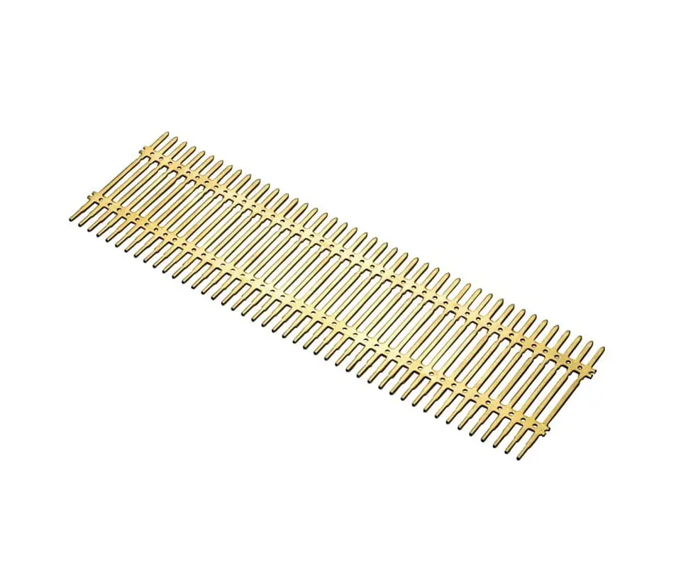
Humidity exposure adds a chemical dimension to the mechanical degradation. After the wash cycle completes and the drum stops spinning, the residual heat from the motor and the water vapor from the laundry create a 40–50°C, 90% RH environment inside the appliance cavity for 30–60 minutes — ideal conditions for condensation on the terminal surface.
This condensation, combined with the residual flux from the wave soldering process used to attach the terminal to the PCB, forms a weak electrolyte that accelerates oxidation of the exposed brass at the fretted crimp interface. Terminals that were designed and qualified for a dry, vibration-free laboratory environment reach end of life within 3–5 years of field use — well inside the 7–10 year consumer expectation for major appliance reliability.
[Compliance Anchor]: Appliance terminals in motor-driven products must pass 1 million vibration cycles at 10–55 Hz with 0.35 mm displacement per IEC 60068-2-6, with contact resistance measured at the wire crimp before and after testing — terminal-only vibration testing that omits the attached wire conductor understates the fretting damage by not loading the crimp barrel with the wire’s mass and stiffness.
💡 Vibration Qualification Gap: Terminals qualified in a static laboratory environment can develop intermittent high-resistance contacts within 3–5 years of field use — well inside the 7–10 year consumer expectation for major appliance reliability. request a vibration test plan for your appliance terminal geometry at your product’s dominant vibration frequency.
Appliance Safety Standards
Glow-Wire Fire Resistance and Creepage Verification
UL 60335-1 and its IEC counterpart IEC 60335-1 form the safety qualification framework for household appliances, and the terminal contributes to several of the standard’s critical test sequences. Clause 30.2 covers resistance to heat and fire: terminals in unattended appliances that carry current above 0.5 A must be subjected to a glow-wire test at 750°C per IEC 60695-2-11.
The glow-wire tip is applied to the terminal’s insulation support area for 30 seconds, and the test passes only if no flames persist longer than 2 seconds after removal and no burning droplets ignite the tissue paper placed below the sample. This test evaluates the terminal’s contribution to fire propagation during a fault condition — a terminal whose plastic housing ignites under the glow-wire fails even if the terminal itself remains electrically functional.
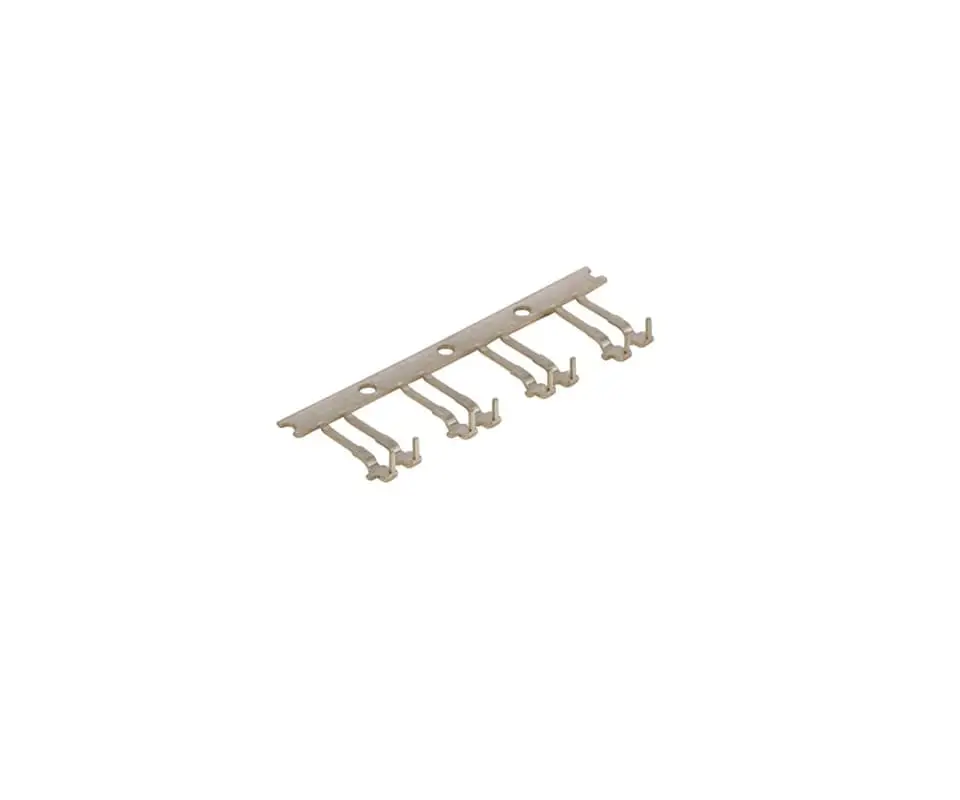
Creepage distance requirements per IEC 60335-1 table 17 govern the spacing between terminals at different potentials. For a 250 VAC appliance operating at pollution degree 2 — normally non-conductive but temporarily conductive due to condensation — the minimum creepage distance is 3 mm between terminals of opposite polarity.
Stamped terminals in compact control boards — increasingly common as appliance manufacturers shrink PCB dimensions — must maintain this spacing after forming, with the formed bend radii and cut-off tabs factored into the creepage path. A terminal whose cut-off tab protrudes 0.5 mm beyond the intended break line reduces the creepage distance to an adjacent terminal by the same amount, potentially dropping below the 3 mm minimum.
For appliance metal stamping in the North American market, UL recognition (RU marking) is the compliance baseline that allows the appliance manufacturer to incorporate the terminal into their UL-listed end product without additional terminal-level testing. This requires the terminal supplier to maintain a UL file with periodic factory inspections by UL auditors — a recurring compliance cost that separates recognized component suppliers from uncertified commodity terminal sources.
[Compliance Anchor]: Terminals in unattended appliances carrying above 0.5 A must pass the 750°C glow-wire test per IEC 60695-2-11 on the production connector assembly, with the terminal’s plastic housing material listed by its UL 94 V-0 flammability rating — testing the terminal alone without its housing understates the fire propagation risk from the combined terminal-housing assembly.
Appliance Stamped Terminal Archetypes
Control board terminals in washing machines, dishwashers, and dryers represent the highest-volume appliance terminal category. Each archetype imposes distinct electrical, mechanical, and plating demands that stamping tooling and material selection must address, from quick-connect force windows to high-temperature element connections to motor drive vibration endurance.
Quick-Connect Control Board Terminals
A single control board contains 20–50 quick-connect terminals — stamped brass tabs 6.35 mm wide and 0.8 mm thick that accept female receptacle terminals crimped to the wiring harness. The terminal’s insertion and withdrawal forces must fall within a 20–50 N window: below 20 N, the receptacle can vibrate off during the appliance’s operation; above 50 N, the assembly operator cannot insert the receptacle without excessive force.
This force window is sensitive to terminal thickness variation — a 0.02 mm overshoot in material thickness increases the insertion force by 5–8 N, pushing it above the 50 N ergonomic limit. Tight gauge control on the incoming brass strip, verified by laser micrometer at the decoiler, maintains the terminal thickness within ±0.01 mm of nominal.

High-Temperature Heating Element Terminals
A terminal crimped to a nichrome heating element wire inside a 3 kW oven element reaches 200–250°C at the crimp interface during operation, with the terminal body seeing 150–175°C measured 10 mm from the element. At these temperatures, tin plating is metallurgically unsuitable — the tin-copper intermetallic compound grows at 2–3 µm per 1,000 hours at 150°C, consuming the pure tin layer and exposing the brittle intermetallic to oxidation.
Nickel plating with a minimum thickness of 5 µm replaces tin as the terminal finish, with the nickel providing a diffusion barrier that prevents copper from the terminal base metal from reaching the surface and oxidizing. Stainless steel 304 terminals with no plating are an alternative for the highest-temperature connection points, relying on the chromium oxide passive layer for corrosion resistance.
Motor Drive Vibration Endurance
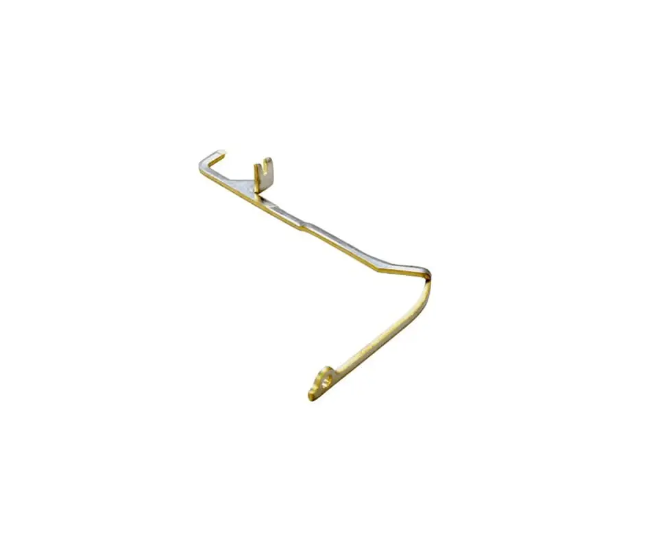
Motor control terminals in home appliance applications — refrigerator compressors, washing machine drive motors, HVAC blower motors — combine vibration with moderate current. A terminal carrying 8 A to a variable-frequency drive motor sees continuous 10–500 Hz vibration from the motor’s rotor imbalance, with the dominant frequency shifting as the drive varies the motor speed.
The terminal’s crimp joint must survive this vibration spectrum without the wire strands fracturing at the crimp exit point, where the combination of vibration and the sharp transition from the crimped to the free wire concentrates bending stress. A formed strain relief feature at the crimp barrel exit increases the flex life of the wire-to-terminal junction by a factor of 5 compared to a straight crimp barrel with no strain relief.
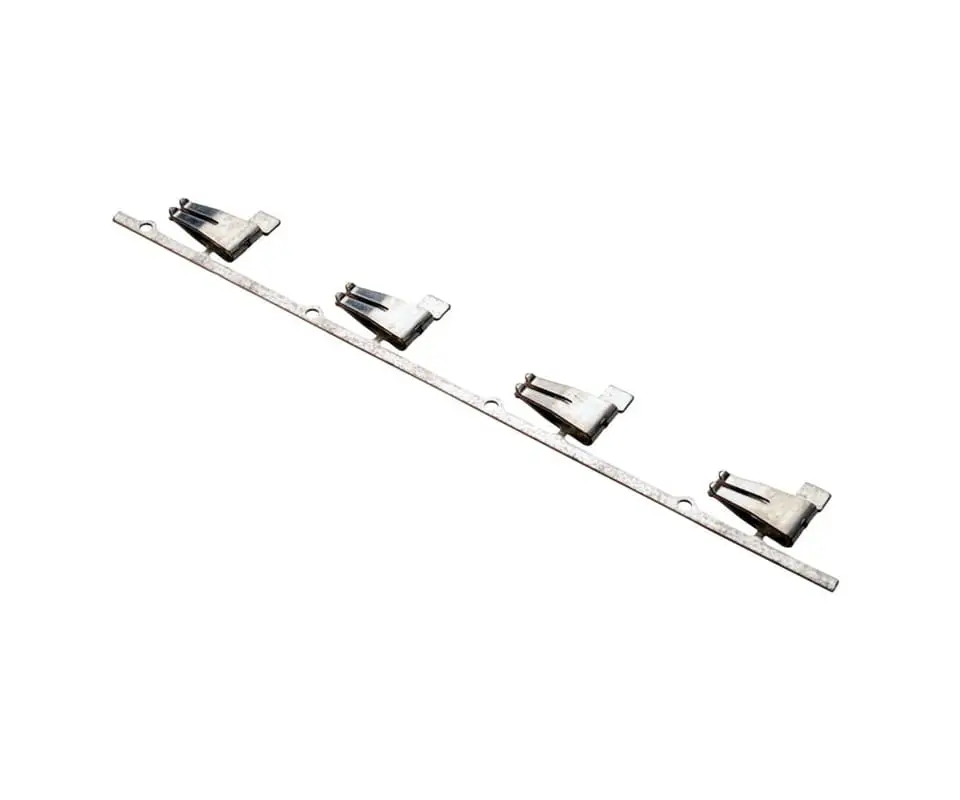
[Compliance Anchor]: Quick-connect terminals must maintain insertion force within 20–50 N and withdrawal force above 15 N after 10 insertion-withdrawal cycles per UL 310, with force measured using a production female receptacle — testing with a polished steel gauge produces artificially low insertion forces that pass terminals rejected by the customer’s production receptacles.
💡 Terminal Selection for Your Appliance Platform: The terminal material, plating, and geometry must be selected for your specific operating environment — a washing machine terminal that works in North America may not survive a European front-loader’s higher spin speed and longer cycle duration. submit your appliance terminal specifications for a platform-specific recommendation validated against your duty cycle and reliability target.
Cost-Optimized Plating & High-Volume Quality
Plating Selection Economics at Million-Unit Volumes
Appliance terminal economics are defined by volume. A terminal that costs $0.003 at 20 million units per year becomes a $60,000 annual line item — enough to attract a cost-reduction mandate from the appliance manufacturer’s procurement team.
The difference between gold plating and tin plating on a 6.35 mm quick-connect tab is approximately $0.002 per terminal. Across 20 million units, that is $40,000 in annual cost difference, and the appliance’s operating environment — dry, indoor, temperature below 85°C — allows tin plating to perform adequately for the 10-year design life.
The engineering decision is to specify tin plating for 95% of appliance terminals and reserve gold for the few applications where the electrical interface — low-level sensor signals — the environment — outdoor condenser units — or the mating cycle count — field-replaceable connectors — demands a noble metal finish.
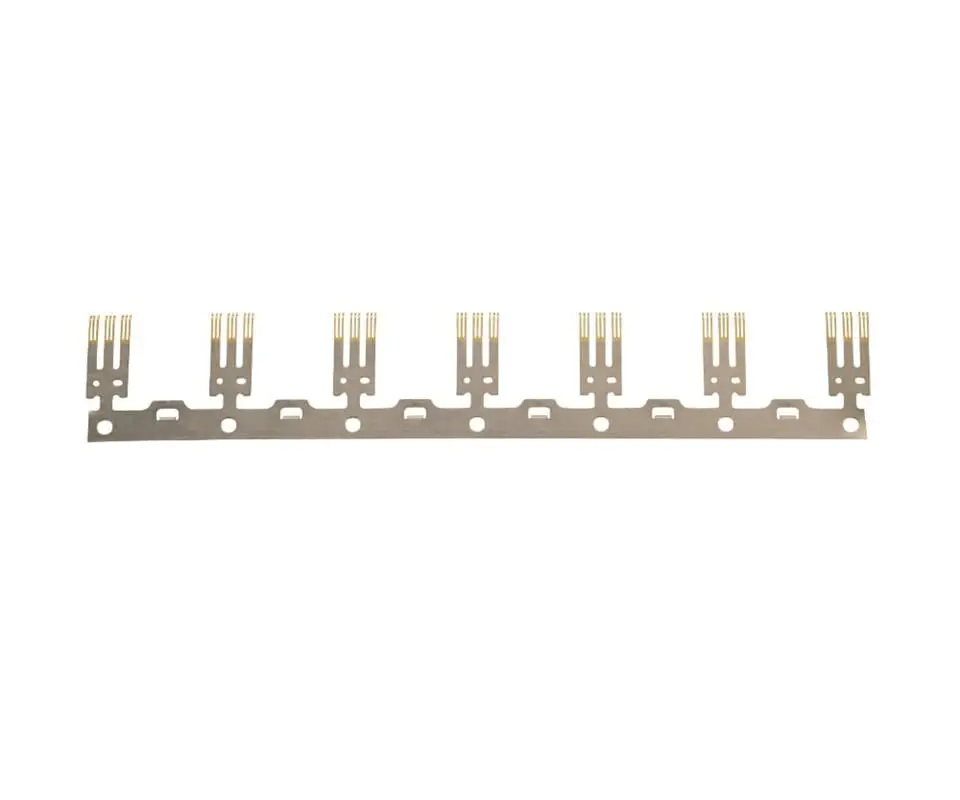
High-volume quality assurance for appliance terminals relies on process capability rather than 100% inspection. At 500 terminals per minute from a progressive die, in-line vision inspection captures critical dimensions — tab width, hole diameter, bend angle — while a sampling plan per ANSI/ASQ Z1.4 verifies material thickness, plating coverage, and insertion force on the finished reel.
Kravzik maintains process Cpk above 1.33 on all critical characteristics through high-volume metal stamping with carbide progressive die tooling that runs 2–5 million strokes between maintenance intervals. The tooling maintenance schedule is driven by SPC trend data rather than a fixed stroke count, with maintenance triggered when the process mean shifts by more than 1.5 sigma from the qualified baseline — a condition that indicates punch wear or die clearance drift before any terminal falls outside the specification limits.
[Compliance Anchor]: Appliance terminal production at volumes above 5 million units per year must demonstrate Cpk above 1.33 for critical dimensions with ongoing SPC monitoring — lot-level acceptance sampling without SPC trend analysis is insufficient because a process drifting toward the specification limit will produce acceptable sample results while generating an increasing percentage of near-limit terminals that fail intermittently in the field.
Compliance Pass
Production terminals sourced from lower-cost suppliers to meet procurement targets can develop intermittent high-resistance connections within 3 years, pushing warranty claims past the 2% threshold. Kravzik stamps appliance-grade terminals with Cpk-validated process control, shipping every lot with SPC trend data and UL-recognized component documentation.
Send us your terminal specifications for a high-volume qualification package, including SPC capability data and UL component recognition documentation.
Related Engineering Resources
- Brass C26000 properties and tin plating adhesion for high-volume terminal production in brass material property data sheets
- Reel-to-reel selective tin plating for cost-optimized appliance terminals in industrial tin plating services
- Carbide progressive die tooling for high-volume appliance terminal stamping in high-volume metal stamping services