Signal Integrity at GHz: Telecom Stamped Electrical Terminals Engineering Guide
A 5G base station terminal that passes DC testing at room temperature can generate bit errors at 28 GHz after six months of outdoor thermal cycling. The failure triggers unnecessary truck rolls to remote cell sites with no obvious hardware fault.
In this guide, you will learn contact resistance stability for telecom-grade stamped terminals at gigahertz frequencies. You will also find GR-63-CORE compliance and material selection criteria for outdoor environments.
Read on for the full engineering guide.
Environmental Attack Vectors
Telecom terminals operate in environments that combine thermal extremes with chemical aggression. A remote radio unit mounted on a rooftop in Shenzhen cycles from -10°C on a January night to 75°C inside the sealed enclosure on a July afternoon, with 90% relative humidity throughout the summer monsoon season. This combination of heat and moisture accelerates two degradation mechanisms simultaneously: fretting corrosion at the separable contact interface driven by differential thermal expansion, and creep corrosion of the copper base metal through micro-pores in the gold plating.
The corrosion product — copper sulfide formed from hydrogen sulfide and sulfur dioxide in urban air — is a semiconductor that creates a non-linear resistance path across the contact interface, invisible to a DC milliohm meter but catastrophic for signals above 1 GHz where skin effect confines current to the outer 2 µm of the contact surface.
Mixed-Flow Gas Corrosion Mechanisms
Mixed-flow gas testing per IEC 60068-2-60 method 4 replicates this urban-industrial atmosphere in accelerated form. Terminals are exposed to 500 ppb hydrogen sulfide, 200 ppb nitrogen dioxide, 20 ppb chlorine, and 200 ppb sulfur dioxide at 25°C and 75% RH for 20 days. Terminals using a 0.75 µm gold flash over nickel — a cost-reduction approach common in indoor-rated connectors — develop visible corrosion spots within 5–7 days of MFG exposure.
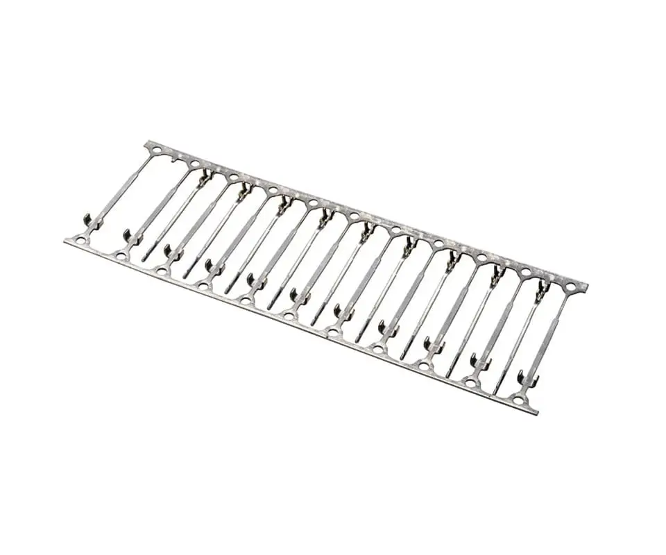
Telecom-grade terminals demand a 1.25 µm minimum gold thickness over a 2.5 µm minimum nickel barrier to survive the full 20-day exposure with less than 5 milliohms of contact resistance drift.
[Compliance Anchor]: Telecom terminals in outdoor and uncontrolled environments must demonstrate contact resistance drift below 5 milliohms after 20 days of mixed-flow gas exposure per IEC 60068-2-60 method 4, measured at 0.1 A using gold-plated probes — DC measurements at higher currents mask the semiconductive corrosion layer that causes RF insertion loss.
💡 Corrosion Risk Audit: Indoor-rated gold flash terminals fail MFG testing within 5–7 days — request an MFG corrosion test on your current terminal supplier’s parts before committing to outdoor deployment.
Network Equipment Standards
Telecom infrastructure certification operates through a hierarchy of standards that flows from network-level reliability requirements down to component-level qualification. GR-63-CORE defines the environmental criteria for network equipment in outside plant and central office environments, including the thermal cycling profile, humidity exposure, and mixed-flow gas corrosion testing that component suppliers must meet.
For connectors and terminals, IEC 60512 provides the detailed test sequences for electrical continuity, contact resistance, and insulation resistance under environmental stress. The supplier must demonstrate that the terminal, when assembled in the customer’s connector housing, passes the full GR-63-CORE environmental sequence without exceeding the contact resistance limits defined in the connector’s detail specification per IEC 61169-1.
NEBS Level 3 Environmental Qualification
Sealing requirements add a mechanical layer to the compliance stack. Outdoor base station connectors rated IP67 per IEC 60529 must prevent water ingress after 30 minutes of immersion at 1 meter depth. The terminal itself is not the sealing element — the connector housing provides the environmental seal — but the terminal’s dimensional stability under thermal cycling determines whether the housing seal remains effective. A terminal that shifts by 0.05 mm due to stress relaxation in the crimp zone can create a gap between the housing and the cable gland seal, allowing moisture ingress that corrodes the entire connector interior within a single wet season.
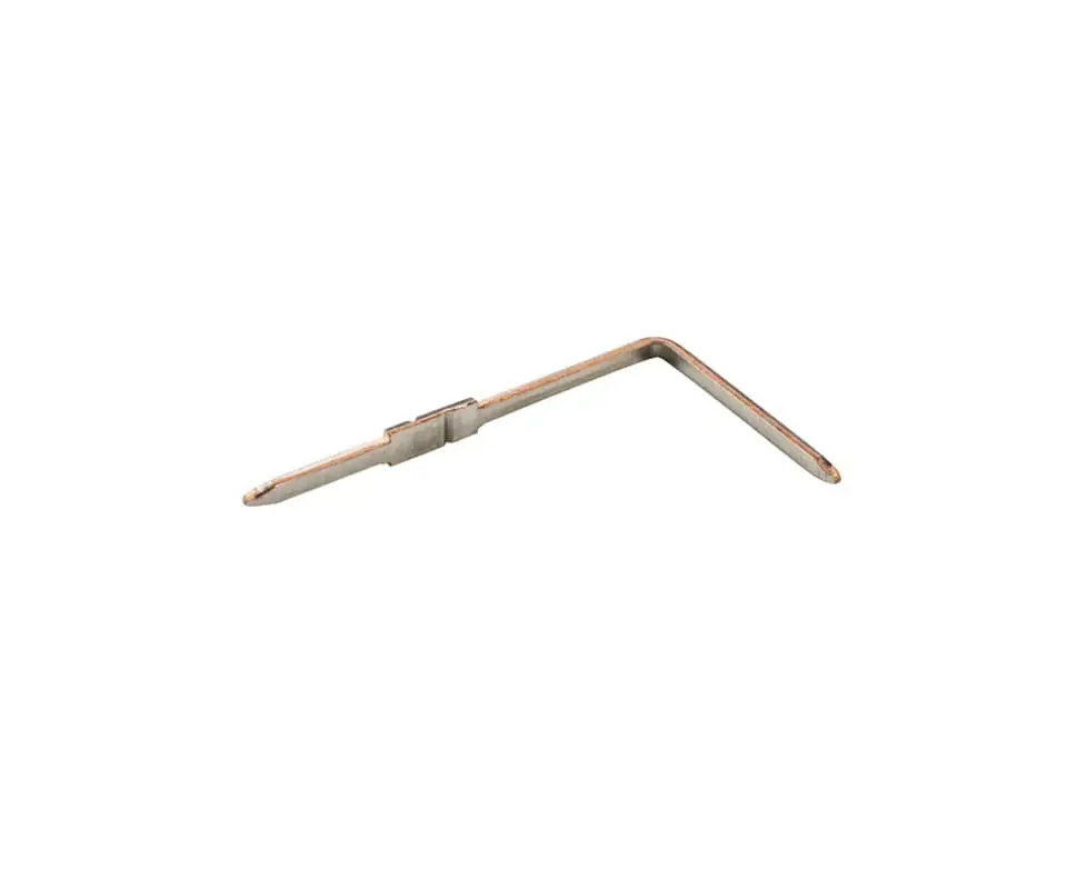
For telecom metal stamping suppliers serving the North American market, NEBS Level 3 certification per GR-63-CORE is the compliance floor. This requires the terminal to maintain specified electrical performance through a thermal cycling profile of -40°C to +70°C for outdoor equipment, with operational testing at temperature extremes — not only post-exposure measurements that miss the intermittent failures caused by differential thermal expansion during live traffic.
[Compliance Anchor]: Telecom terminal qualification per GR-63-CORE section 4.2 requires contact resistance measurement at temperature extremes during thermal cycling, not only before and after — intermittent high-resistance events masked by post-test ambient measurements account for the majority of “no fault found” field returns in outdoor base station connectors.
Telecom Stamped Electrical Terminal Archetypes
Backplane connectors in baseband units and radio units represent the most demanding telecom terminal application. These high-density connectors pack 100+ differential pairs into a single housing, with stamped terminal pitch as tight as 1.8 mm. Each terminal pair must maintain differential impedance of 100 ±10 ohms from DC to 28 GHz, a requirement that depends on precise control of the terminal cross-section, plating thickness, and the air gap between the signal and ground terminals. A 5 µm over-etch during the stamping process reduces the terminal width by 2%, shifting the impedance above the 110-ohm upper limit and degrading the return loss at the upper end of the frequency band.
RF Coax Center Contact Durability
RF coax connector center contacts form a distinct category. These cylindrical stamped contacts mate with a solid or stamped outer conductor to form a 50-ohm transmission line, with the contact diameter setting the impedance through a precise ratio to the outer conductor ID. The stamped center contact requires gold plating over nickel on phosphor bronze C51000, with the gold thickness typically 1.25–2.5 µm to survive 500 mating cycles without exposing the nickel underlayer. A worn-through gold layer exposes nickel, which forms a resistive oxide layer under the combination of atmospheric sulfur and elevated humidity — producing the intermittent signal degradation that field technicians describe as “the connector that works after you unplug and replug it.”

Power Distribution Terminal Thermal Management
Power distribution terminals in rectifier shelves and battery backup units operate at 50–200 A DC with temperature rises up to 50°C above ambient. These terminals use thicker brass or copper alloys with silver or tin plating, where the primary failure mode shifts from signal integrity to thermal runaway — a 2-milliohm increase in a terminal carrying 100 A generates 20 W of additional heat, accelerating oxidation and driving the resistance higher. This positive feedback loop makes initial contact resistance qualification at 10% of rated current insufficient for telecom industry power applications. Full-current thermal imaging during type testing reveals hot spots invisible to milliohm measurements at low current.

[Compliance Anchor]: Backplane connector terminal qualification for 28 GHz operation requires time-domain reflectometry measurement of each differential pair within the production connector assembly, detecting impedance discontinuities exceeding 5 ohms that correspond to terminal geometry deviations below 10 µm — a threshold invisible to dimensional inspection alone.
💡 Impedance Control Validation: A 5 µm over-etch during stamping shifts differential impedance past the 110-ohm upper limit — submit your connector geometry for a production-representative TDR measurement on assembled connector pairs.
Corrosion Defense & Plating Integrity
Gold plating thickness is the single largest cost driver for telecom terminals, and the most common target for cost-reduction efforts that backfire in the field. A connector specified with 1.25 µm minimum gold at the separable interface may arrive from an alternate supplier with 0.75 µm of gold applied to the entire terminal surface — a substitution that passes visual inspection and initial contact resistance testing but fails after 7–10 days of MFG exposure. Kravzik validates gold plating integrity through nitric acid vapor porosity testing per ASTM B735 on production terminals pulled from each plating lot, detecting micro-pores in the gold layer that provide corrosion pathways to the nickel underlayer and copper substrate.
Selective Gold Plating Process Control
Selective gold plating on the mating zone — rather than full-body gold — offers a cost compromise for telecom terminals where only the separable interface requires corrosion protection. The transition zone between the gold-plated contact area and the tin-plated tail must remain free of gold-tin intermetallic formation, which occurs when gold thickness in the transition zone exceeds 0.25 µm and the terminal experiences soldering temperatures. Kravzik controls this transition through precision selective gold plating with a brush-plating mask that maintains a gold-free zone of 0.3 mm minimum between the gold contact area and the solder tail, preventing the gold embrittlement that causes solder joint cracking during thermal cycling.
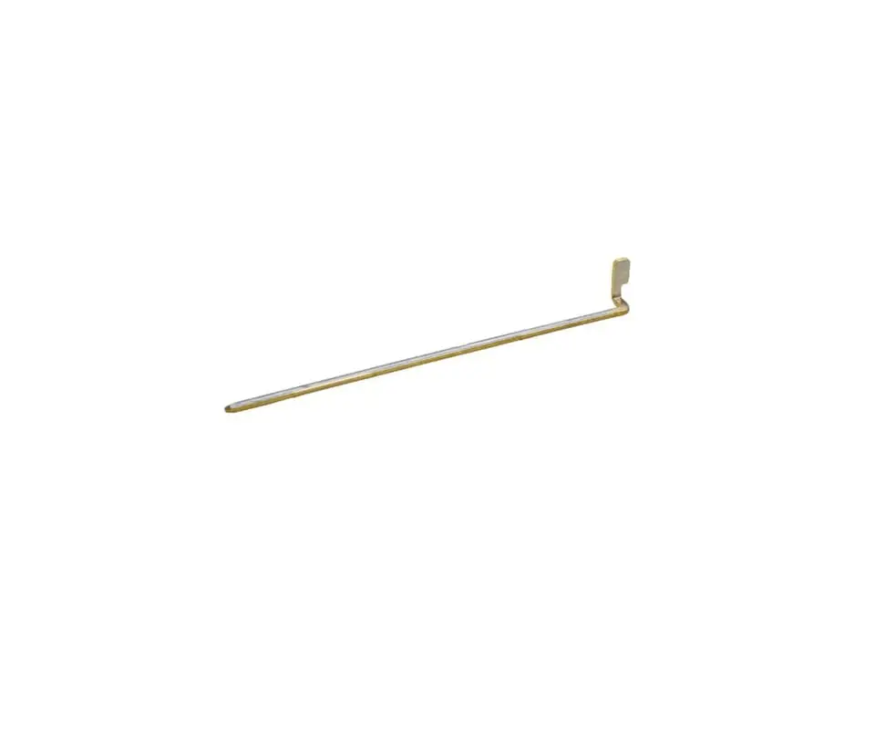
[Compliance Anchor]: Gold-plated telecom terminals must demonstrate zero visible corrosion spots after nitric acid vapor porosity testing per ASTM B735, with a minimum gold thickness of 1.25 µm at the separable interface verified by XRF measurement at the contact point — not averaged across the terminal surface, which masks thin spots at the high-wear contact zone.
Compliance Pass
Terminals passing DC contact resistance testing can develop intermittent high-resistance events during thermal cycling, triggering costly “no fault found” field returns. Kravzik stamps telecom-grade terminals with controlled impedance geometry, shipping every lot with gold thickness XRF reports, porosity certs, and thermal cycling data measured at operating temperature extremes.
Send us your connector specifications for a telecom qualification test package, including GR-63-CORE thermal cycling and MFG corrosion data ready for your NEBS submission.
Related Engineering Resources
- Phosphor bronze and beryllium copper spring properties for high-cycle telecom connectors in copper alloy material property reference
- Gold plating thickness verification and porosity testing for corrosion-resistant telecom contacts in gold and silver plating process capabilities
- High-speed progressive die stamping for backplane connector terminals at 200+ SPM in high-speed progressive die stamping services